Mega Menu
Cálculo de cables
Low voltage
Medium voltage
Low voltage
Installation systems
Installations under conduit
Capacitor bank
Capacitors transformer
Factor C/K capacitors
Frecuencia resonancia condensadores
Media Tensión
Technical specifications
Earth fault current
Earth conductor
CT and VT transformers
Transformer performance
Cambiador tomas
Photovoltaic
Photovoltaic configurator
Inverter comparator
Panel comparator
Curves IV - PV
English
Spanish
Portuguese
French
Italian
Notifications
View All
View More..
Lock Screen
Log In
Menu
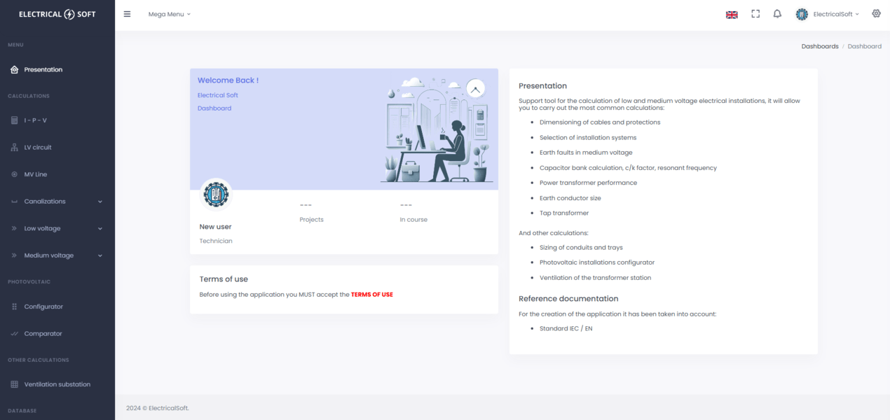
Presentation
Calculations
I - P - V
LV circuits
MV line
Canalizations
Trays
Conduits
Earthing arrangements
Earth conductor
Howe Method
Low voltage
Installation systems
Installations under conduit
Capacitor bank
Capacitors transformer
Factor C/K capacitors
Frecuencia resonancia condensadores
Medium voltage
Technical specifications
Earth fault current
CT and VT transformers
Transformer performance
Tap changer
PHOTOVOLTAIC
Configurator
Charts
Curves IV - PV
Panel curves
Comparator
Inverters
Panels
Other calculations
Ventilation of a substation
Database
Photovoltaic
Inverters
Panels
Cables
Cables 450/750 V
Cables 0.6/1 kV
Cables 12/20 kV
Cables 18/30 Kv
Conduits
Conduits thicknesses
DOCUMENTATION
Low voltage
I-P-V
LV circuits
Capacitor bank
Capacitors transformer
Factor C/K capacitors
Risk of resonance
Medium voltage
Earth fault current
Transformer performance
Tap changer
Canalizations
Trays
Conduits
Earthing arrangements
Earth conductor
Photovoltaic
Photovoltaic
Others
Ventilation TS
Settings
Parameters
Standard reference
Common
Specific LV
Specific MV
Calculation criteria
Application
Permissions
Terms of use
Authentication
Login
Register
Recover Password
Lock Screen
Change Password
Low voltage circuit
Low voltage circuit
LV circuit
1
Conditions
2
Load
3
Cable size
4
Table
Method of installation
Conduit embedded or enclosed
Surface mounted conduit
Trunking (IPX4)
On unperforated tray
On perforated tray
Buried conduit in ground IEC 60364
Directly buried in ground IEC 60364
Mounted on wall or ceiling
Building voids
Tubo en pared aislante
Single-core cable on insulators
Arrangement (cables touching)
Bunched in air, surface, embedded or enclosed
Method
Ambient temperature
10
15
20
25
30
35
40
45
50
55
60
ºC
Depth
---
m
Thermal resistivity
---
K·m/Ω
Short circuit
kA
Isc duration
0.1
0.2
0.3
0.4
0.5
0.6
0.7
0.8
0.9
1.0
1.1
1.2
1.3
1.4
1.5
1.6
1.7
1.8
1.9
2.0
2.1
2.2
2.3
2.4
2.5
2.6
2.7
2.8
2.9
3.0
3.1
3.2
3.3
3.4
3.5
3.6
3.7
3.8
3.9
4.0
4.1
4.2
4.3
4.4
4.5
4.6
4.7
4.8
4.9
5.0
s
Power
Current
Copper
Aluminium
Single-core
Multi-core
Resume
Supply
3P+N+PE
3P+N/2+PE
3P+N
3P+N/2
3P+PE
1P+N+PE
1P+N
L-L+PE
L-L+
Voltage
*
V
SINGLE-PHASE
Insulation
PVC
XLPE
EPR
Number
*
Power
*
kW
Cos φ
*
Third harmonic
%
Utilization factor
*
Simultaneity factor
*
Length
*
m
Max voltage drop
*
%
Additional circuits
0
1
2
3
4
5
6
7
8
9
10
11
12
13
14
15
16
17
18
19
20
Conductors per phase
1
2
3
4
5
6
7
8
9
10
11
12
Minimum size
1.5
2.5
4
6
10
16
25
35
50
70
95
120
150
185
240
mm²
Clearance
---
m
kr grouping
*
Protection
Circuit breaker IEC 60898
Circuit breaker IEC 60947-2
Fuse gG/gL
Fuse gPV
---
Current rated
2
4
6
10
16
20
25
32
40
50
63
80
100
125
160
200
250
320
400
500
630
800
1000
1250
1600
2000
2500
3200
4000
5000
6300
A
Ir (x In)
0.40
0.50
0.60
0.70
0.80
0.85
0.90
0.95
0.98
1.00
Resume
Sph (mm²)
Ia (A)
Ib/Ia (%)
Drop (%)
Ir (A)
Isc (kA) [0.1s]
---
---
---
---
---
---
Delete
Save
(
)
Settings
Choose Layouts
Light Mode
Dark Mode
RTL Light Mode
Dark RTL Mode